FAQ
Switches
Seal ratings
Digital phase meters
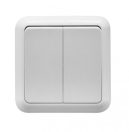
Single Pole Switch:
The single pole switch is the general purpose workhorse of switches. Single pole switches turn a light, receptacle or device on and off from a single location.
2 Pole Switch
The double pole switch also has "on" and "off" markings and functions similar to a single pole switch in that it turns something on and off from one location. However, because it has four brass terminals instead of two terminals it can handle switching two wires (neutral, phase)
Change over Switch
The three way switch is always used in pairs and allows you to turn a light or receptacle on and off from two different locations.
Cross over Switch
The four way switch is used in between two change over switches to control an outlet or light fixture from three different locations
What are the different seal ratings and what do they mean?
Definition of IP Codes (Ingress Protection):
IEC (International Electrotechnical Commission) 60529 Standards document specifies an international Classification system for the sealing effectiveness of enclosures of electrical equipment against the "Intrusion into the equipment of foreign bodies and moisture".
First Digit (intrusion protection)
- No special protection. Not rated (or no rating supplied) for protection against ingress of this type.
- Protection from a large part of the body such as a hand (but no protection from deliberate access); from solid objects greater than 50mm in diameter.
- Protection against fingers or other object not greater than 80mm in length and 12mm in diameter (accidental finger contact).
- Protection from entry by tools, wires etc, with a diameter of 2.5 mm or more.
- Protection against solid objects larger than 1mm (wires, nails, screws, larger insects and other potentially invasive small objects such as tools/small etc).
- Partial protection against dust that may harm equipment.
- Totally dust tight. Full protection against dust and other particulates, including a vacuum seal, tested against continuous airflow.
Second Digit (moisture protection)
- No protection.
- Protection against vertically falling droplets, such as condensation. ensuring that no damage or interrupted functioning of components will be incurred when an item is upright.
- Protection against water droplets deflected up to 15° from vertical
- Protected against spray up to 60° from vertical.
- Protected against water splashes from all directions. Tested for a minimum of 10 minutes with an oscillating spray (limited ingress permitted with no harmful effects).
- Protection against low-pressure jets (6.3 mm) of directed water from any angle (limited ingress permitted with no harmful effects).
- Protection against direct high pressure jets.
- Protection against full immersion for up to 30 minutes at depths between 15 cm and 1 metre (limited ingress permitted with no harmful effects).
- Protection against extended immersion under higher pressure (i.e. greater depths). Precise parameters of this test will be set and advertised by the manufacturer and may include additional factors such as temperature fluctuations and flow rates, depending on equipment type.
- (K): Protection against high-pressure, high-temperature jet sprays, wash-downs or steam-cleaning procedures - this rating is most often seen in specific road vehicle applications (standard ISO 20653:2013 Road Vehicles - Degrees of protection).
IPX Ratings
Not an entirely valid IP rating, the "x" simply denotes that the value for that number is missing. You can replace it with a zero, assuming that it has not ingress protection rating. This may not be the case, but better safe than sorry. The first number denotes foreign body ingress protection, the second moisture. So "x"5 for example, means that there is no defined protection from solid objects, but protection against low pressure water jets, while 5"x" would denote partial protection from dust, but no particular protection from moisture.
Digital phase meters
A special electronic circuit, by the flow of current and applied voltage generates pulses in proportion to the energy consumed. Phase energy consumption is signaled by a flashing LED. The number of pulses is converted into energy input and its value is indicated on the LCD display


